
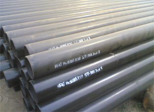
steel pipe structure for the inspection
Home >
-
API steel pipe
- API steel pipe
- API steel casing pipe
- Casing and Tubing
- API drill pipe
- API5L steel pipe
- Oil pipeline
-
Carbon steel pipe
- Carbon steel pipe
- Welded steel Pipe
- seamless carbon steel pipe
- Petroleum Casing Pipe
-
Alloy steel pipe
- astm a 335 gr p22
- alloy steel pipe l555
- 25crmo4 alloy steel pipe
- alloy pipe a335 p11

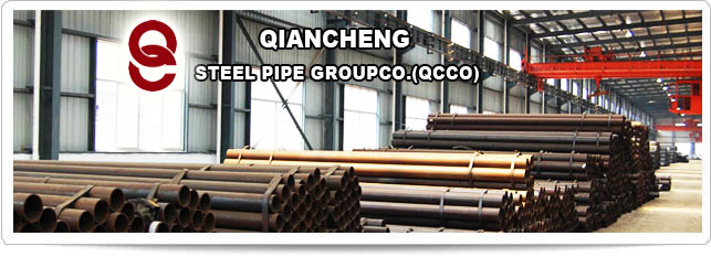
One of the Top 500 enterprises in China foreign trade
QCCO was approved as a member of “China Association for Contracting Projects Abroad “and granted a membership certificate on Sep 28,2005; “Credibility Rating AAA certificate in Foreign Trade” was granted to QCCO by China Shippers’ Association
steel pipe structure for the inspection
Scope This standard applies to the transmission line steel pipe pole and substation configuration stent manufacturing inspection procedures.
Second, the reference to the standard DL/T646-2006 "power transmission steel pipe structure manufacturing technical conditions" JG / J 03-2004 "power transmission steel pipe structure manufacturing internal control technical conditions JB/T7949-1999" steel structure weld Dimensions "GB50205-2001 steel structure engineering construction and acceptance GB11345-89 steel weld manual ultrasonic flaw detection method and classification of testing results" GB/T13912-2002 "metal covering layer of iron and steel products hot-dip galvanizing technology requirements", testing tools testing tools rectangular device, ruler, level, ruler, feeler, tape measure, calipers, angle ruler, welding Every test feet, gage, cover die, pull. Responsibilities the 4.1 quality inspector responsible for the company's product quality inspection to ensure the realization of the company's quality goals.
4.2 component hot-dip galvanized galvanized a full-time quality inspector inspection. 4.3 Checking the workshop procedure operator first inspection records. 4.4 flaw detection test by testing a full-time quality inspector. 4.5 The quality inspector should regularly provide quality inspection information, accurate to the safety and quality and relevant departments to provide information support for the company's quality management decisions. 4.6 complete other tasks assigned by the Quality Engineer. Must be strictly in accordance with the standards, process documents, drawings and quality inspection instructions to test the quality of products and to make compliance with the judgment. Test content 5.1 Appearance inspection of steel the appearance test surface without cracks, folding, scarring folder slag and heavy leather surface rust, pitting and scratches when the depth of the steel negative allowable deviation value shall not be greater than 1/2 and local steel surface the defects accumulated greater than the area of the steel for return processing. The steel end side or the fracture should not be hierarchical, slag and other defects. 5.2 blanking 5.2.1 to test its quality certification specifications Dimensions appearance quality of raw materials meet the requirements. 5.2.2 crossed meet the requirements of drawings, samples and small.
5.2.3 cut in accordance with the thickness of the the drawing size steel tape measure board length and width of the plate and measured with a vernier caliper. Table 1. Measuring diagonal are equal. Table cutting the allowable deviation units mm No. Item allowable deviation schematic diagram to a total of 12 2-disc D Jiangsu Xiangyu Electric Power Equipment Manufacturing Co., Ltd., a part of basic dimensions length L ± 2.0 width b ± 2.0 JG / J 06-2005 2 / 100 and not greater than 3mm 5.2.4 Measuring the edge of the plate vertically with foot rectangular side leaning above or below the edge of the board at the board with a ruler to measure the distance between the foot rectangular. Shown in Table 2 Table 2 steel plate cutting end face tilted to allow deviation in mm No. steel plate thickness allows deviation p schematic diagram 1 20 ≥ t 1.0 2 36 ≥ t20 1.5 t36 1.5 5.2.5 Measuring tube with the end face of the vertical right angle ruler leaning against the side of the tube above or below the edge in the distance with a ruler measuring board between the foot rectangular. Table 3 Table 3 steel pipe cutting end face inclination allowable deviation units 1.0 2 180 ≥ 1.5 3 400 ≥ D95 D180 2.0 4 D400 2.0 5.3 machined 5.3 mm No. steel pipe diameter D allows deviation p schematic diagram 1 95 ≥ D. 1 steel flange inside diameter, outside diameter tape measure to comply with the requirements of the thumbnail. 5.3.2 round bar with a vernier caliper measurement of size, flange thickness dimensions deviation shall conform to the requirements of the drawings and the "power transmission steel pipe structure manufacturing internal control technical conditions. 5.4 Pipe 5.4.1 of steel plate to bend its edges should be smooth transition surface without damage, the folds and concave scratches depth should not be greater than 0.5 mm.
5.4.2 Pipe allowable deviation in Table 4 Table 4 Item deviation allowable deviation in mm steel pipe rod segment manufacturing name allows deviation mm diagram a steel-made pipe diameter D docking connector D ≤ 500 ± 1.0 D500 ± 2.0 plug the connector ± D/100 without greater than ± 3.0 flange connection ± 3.0 2 steel pipe roundness butt joints D ≤ 500 1.0 D500 2.0 docking connector D/100 ≤ 3.0 pt Jiangsu Xiangyu Electric Power Equipment Manufacturing Co., Ltd. JG / J 06-2005 3 of 12 flange connection the 3.0 edge width b ± 2.0 polygon steel pipe system through an angle α ≤ 1 ° 4 the same cross-section on the side of size D butt joints D ≤ 500 ± 1.0 D500 ± 2.0 plug connector ± D/100 and not greater than ± 3.0 at ± 3.0 5 local salience or depression ≤ 2.0 ff 6 single rod segments up and down the two-section axial torsion α α ≤ the 40 datum α 5.5 hekou 1 steel tape measure measurement error is equal to the diagonal, edge. Ruler to measure their counterparts in the wrong side, the weld longitudinal displacement, gap. See Table 5 Table 5 No. Item allowable deviation Legend 5.0 2 counterparts the wrong side of a longitudinal weld every longitudinal displacements t/10 ≤ 3.0 3 gap 1.0 5.6 hole on a steel tape measure any two hole distance between the total distance of the holes, France Lan hole distance between the flange hole center diameter. See Jiangsu Xiangyu Electric Power Equipment Manufacturing Co., Ltd., JG / J 06-2005 4 12 Table 62 vernier caliper hole public that diameter, hole below the diameter difference, roundness. See Table 63 hole on the surface to be concave surface defects greater than 0.2 mm burr should clear the allowable deviation of the hole on the provisions of Table 6. Table 6 hole on the allowable deviation units mm No. Item allowable deviation diagram a nominal diameter d before galvanizing galvanized after 0.8 0 0.5 -0.1 2 roundness dmax-dmin ≤ 1.0 3 holes up and down diameter difference d1-d ≤ 0.12t 4 hole The verticality P 0.03t, and ≤ 1.0 in the same group between two adjacent holes within a distance of the S1 ± 0.7 in the same group between two adjacent holes distance S2 ± 0.5
The two hole distance S3 ± 1.0 nonadjacent group two holes distance connection flange holes S4 ± 1.5 6 S ± 0.5 connection distance between the center of the flange hole diameter D ± 1.0 7 foot flange hole distance the SD ≤ 1500 ± 1.5 D1500 + 2.0 feet flange hole center diameter D ± 2.0 8 margins Sg ± 1.5 Note 1. No. 1,2 deviation should not exist. 2 position measurement of the punched holes in its trails where the plane. When the plate thickness is larger than the aperture or material for carbon steel plate thickness greater than 16mm, made of low-alloy steel plate thickness greater than 14mm punching should be adopted should not be used when drilling. Jiangsu Xiangyu Electric Power Equipment Manufacturing Co., Ltd. JG / J 06-2005 Page 5 of 12 5.7 welding with weld inspection ruler to measure the weld height, width. As shown in Figure 1-2-3 and Table 7. 2 visual appearance of defects. See Table 83 weld inspection ruler and the ruler measurements the weld edge of the vertical degree. See Table 94 weld inspection weld ruler measuring angle diagonal size. See Table 10 I-shaped groove butt welds, including I-shaped with a backing plate butt weld shown in Figure 1 weld width cb2a. I-shaped groove butt welds shown in Figure 2 of the weld width Cg2a. Figure 1 Figure 2 weld surface irregularities allowable deviation value of weld reinforcement weld any 25mm length within 2.0mm Figure 3 Table 7 units mm welding method weld form weld width C submerged arc weld reinforcement h Cmin Cmax b value of the I-shaped weld welding Ⅰ shaped weld b8 b28 03 g4 g14 manual arc welding and gas metal arc welding of Ⅰ shaped weld b4 b8 downhand 03 the rest of the 04 non-I-shaped weld g4 g8 Note table in line with GB985, GB986 the actual assembly of the value of the standard requirements. Table 8 weld quality grade and defect classification in mm project to allow deviation weld quality grade one two three internal defects in ultrasonic testing assessed the grade Ⅱ Ⅲ ------ Inspection Level B grade Class B ----- - the Jiangsu Xiangyu Electric Power Equipment Manufacturing Co., Ltd. JG / J 06-2005 6 a total of 12 testing ratio 100 20 ------ external defects is not welded full inadequate design requirements do not allow or ≤ 0.20.02t and ≤ 1.0 ≤ 0.20.04t and ≤ 2.0 per 100.0 contraction of the the defect total length is less than or equal to 25.0 roots within the weld does not allow ≤ 0.20.02t and ≤ 1.0 ≤ 0.20.04t ≤ 2.0 length not limited to undercut not allowed ≤ 0.05t and ≤ 0.5 continuous length ≤ 100.0 and weld both sides of the bite the edge total length ≤ 10 weld full length ≤ 0.1t ≤ 1.0 unlimited length crack crater cracks are not allowed not allowed allow individual length ≤ 5.0 arc crater cracks abrasions are not allowed allow exist the individual arc scratches splash clear clean joints bad does not allow gap depth ≤ 0.05t ≤ 0.5 notch depth ≤ 0.1t ≤ 1.0 1000.0 weld shall not be more than one welding tumor does not allow the surface slag does not allow deep ≤ 0.2t long ≤ 0.5t ≤ 20.0 surface pores are not allowed allowed every 50.0 weld diameter ≤ 0.4t ≤ 3.0 stomatal two Pitch ≥ 6 times the aperture thickness of the fillet weld the design weld thickness meter ------ ≤ 0.30.05t ≤ 2.0 100.0 weld defects within the total length ≤ 25.0 Table 9 weld edge straightness f at any 300mm continuous weld length of its value in line with the provisions of the following table in mm welding method weld edge straightness deviation f submerged arc the 4.0 manual arc welding and gas shielded arc welding Table 10 units 3.0 mm welding method size deviation K12 K ≥ 12 submerged arc 4.0 5.0 manual arc welding and gas metal arc welding 3.0 4.0 5.8 welding assembly Jiangsu Xiangyu Electric Power Equipment Manufacturing Co., Ltd. JG / J 06-2005 7 12 weldment assembly allowable deviation provisions in Table 11. Table 11 weldment assembly allows deviation units mm No. Item allowable deviation diagram 1 flange facing axis tilt P the D2000 3.0 connection plates Displacement e hole 1.0 nonporous 3.0 3 connecting plate tilt P the hole 1.0 nonporous 2.0 4 steel pipe vertical the weld longitudinal displacement e 2.0 5 butt joints wrong mouth δ / 10 and ≤ 2.0 6 gap straightness of a 1.0 7 f L/1500 ≤ 3.0 8 member length the L steel pipe rod L/1000 Square steel, pipe tower and steel pipe substation Supporting Structure ± b ± 1.0 14 verticality P 200 2.0 9 height h ± 1.5 10 the verticality P 100 and ≤ 1.0 11 center offset e ± 1.5 12 box-shaped cross-section height h ± 1.5 13 box-shaped cross-section width ≤ 2.0 δ Jiangsu Xiangyu Electric Power Equipment Manufacturing Co., Ltd. JG / J 06-2005 8 12 15 steel pipe rod cross arm seat center offset e 3.0 16 two sets of adjacent connecting plate spacing a ± 2.0 17 two sets of adjacent connecting plate spacing the a1 ± 3.0 18 Substation Framework node capitals board flatness ≤ 2.0 19 intersecting connection between the supervisor and the branch pipe angle α ± 0.5 ° 20 executives and branch pipe flange distances a1, a2 ± 2mm in charge of the direction of the longitudinal centerline manifold method blue distance a ± 2mm the 22 variable slope site supervisor manifold flange distance ipsilateral distance requirements at the same time to increase or decrease a the a1 ± 3mm 23 in charge of the left and right branch pipe flange from a ± 2mm the 24 manifold flange offset e ± 2mm 25 manifold length L ± 1.5mm final inspection 6.1 sets mode rod the two stuck one way or another line measurement component straightness first mode with sets of two of the tube is fixed to take the same point of cable with a ruler measuring tube in line the distance between the. See Table 6.2 the pull beam, with a line of two with a ruler to measure the beam to arch size. 6.3 The steel tape measure the root opening, and a tube amount from the leftmost to the rightmost one the distance between the tubes.
6.4 steel measuring tape to measure the length of the member. See Table Electric Power Equipment Manufacturing Co., Ltd. JG / J 06-2005 9 12 6.5 12 foot rectangular horizontal ruler measuring the connecting plate center offset first horizontal ruler measurement board is parallel with the rectangular device measuring board offset value. See Table 12 6.6 flange first horizontal axis tilt tube is level with the level of foot tape measure measuring flange is level. See Table 12 6.7 with a feeler gauge to measure the gap between the two flanges ensure deviation of 0.8 mm. Table 12 final inspection mm No. Item allowable deviation units allowable deviation schematic diagram 1 flange connection steel pipe rod length LL/1000 fL 2 steel pipe rod straightness f L/1500 3 steel pipe rod plug length L 0 L/10 4 bayonet Square steel, pipe rod plug surface bonding rate ≥ 75 perimeter edge local clearance ≤ 5.0 5 steel pipe rod cross-dan, the vertical displacement of the stent end e crossarm bracket on the vertical centerline of the main material degree L / 1506 ipsilateral adjacent cross Tam ends of the vertical distance the distance between a same section crossarm 5.0 0 the 7 steel pipe rod cross arm bracket in the same plane horizontal displacement e 3L/1000 and ≤ 5.0
8 flange connection of local clearance a steel pipe rod the ≤ 3.0 steel pipe tower and steel pipe substation constitutive bracket ≤ 2.0 9 flange counterpart wrong side of e ≤ 2.0 Jiangsu Xiangyu Electric Power Equipment Manufacturing Co., Ltd. JG / J 06-2005 Section 10 page 12 10 architecture Liangheng Liang center vertical displacement f ± L/2000 11 24000 24000 3.0 -5.0 5.0 -7.0 width total length L ≤ b ± 3.0 cross-section height h ± 3.0 hanging point distance L1 ± 5.0 12 structure plane distortions 10.0 L1L 13 Root opened size L ≤ L/2000 14 root on diagonal size L1 ≤ L1/2000 15 cross arm hanging point horizontal distance allowable deviation ± 5.0 16 steel pipe tower vertical deviation ≤ H/750 6.8 appearance of the coating should be uniform stomata or substrate exposed spotted that there was no attachment or attached to solid metal molten particles and affect the service life and application of the coating defects. 6.9 acid, liquid zinc during use should be appropriate request to the acid concentration, temperature, liquid zinc in iron and aluminum content inspection. 6.10 magnetic measuring magnetic gauge to measure the coating thickness values thinnest part measuring averaged. Table 13 - the measuring surface not less than 1 c ㎡ only one measurement - should be in the cross-section of the coating by microscopy of straight lines and curves measuring 12cm distance measuring an average of ten times the arithmetic average.
- Measuring the diameter of the surface of greater than 5mm, only one measurement. - Measuring surface diameter between 35mm should be 1 c ㎡ secondary measurements and the arithmetic mean. - Measuring surface diameter of less than 3 mm and the arithmetic mean of three measurements should be within 1 c m. - Point measurement method should 1c ㎡ five measurements and the arithmetic mean. Table 13 in mm measured position of the test methods used and the number of datum size Jiangsu Xiangyu Electric Power Equipment Manufacturing Co., Ltd. JG / J 06-2005 11 12 only one measurement measuring surface than 1c ㎡ 1 to 2cm the equalization measuring distance of ten times the arithmetic average of the microstructure of the coating cross section linear measurement only one measurement of the diameter of the measuring surface in the second measured between 510mm the arithmetic mean of the diameter of the measuring surface in the three measurements between 35mm arithmetic the average diameter of the measuring surface less than 3mm Jiangsu Xiangyu Electric Power Equipment Manufacturing Co., Ltd. JG / J 06-2005 12 of 12 five times the arithmetic mean of measuring surface measurement points 6.11 a different inspection levels asked to select the test surface . impermissible defects b local testing of weld testing should be added in the extension of the weld site to add length should not be less than the length of the weld length of 10 and should not be less than 200mm when there are defects that are not allowed Addressing the 100 testing and inspection of the weld. Perform testing according to GB11345-89 "weld manual ultrasonic testing methods and classification of testing results" standard.
上一篇:Square steel pipe, rectangular steel pipe carrying capacity
下一篇:45 # SMLS pipe price ,16mn pipe price, Q345B SMLS pipe price